The phases are denoted by in that order.
Why 3-phase?
Section titled “Why 3-phase?”Why not 1-phase?
Section titled “Why not 1-phase?”- The current can be distributed into 3 wires instead of just 1.
There is a maximum limit of how much current a wire can carry. - Economical as less amount of wires.
3-phase system requires wires ( if balanced) while single phase system requires .
Why not 2 or 4 or 6?
Section titled “Why not 2 or 4 or 6?”- Generators are volume constrained.
3-phase system has the most optimum volume utilization in a generator. - 3-wired 3-phase system carry 3 times the power of a 2-wired 1-phase system.
- As number of phases increases, the power advantage diminishes.
- As number of phases increases, the complexity of construction and maintanance increases.
- 3-phase motors have the most optimum volume utilization for a given output.
Balanced 3-phase
Section titled “Balanced 3-phase”A 3-phase system is said to be balanced iff:
- Supply is balanced
- Loads are the same in each phase
Power source
Section titled “Power source”A 3-phase power source which produces 3 phase voltages of equal rms value, but with phase difference.
Phasor diagram
Section titled “Phasor diagram”A graphical representation of the magnitude and phase relationship between different waveforms.
In a balanced 3-phase system, the phasor diagram shows three phasors (vectors) of equal length, separated by 120° angles. Each phasor represents the voltage of one phase. The diagram helps in visualizing the phase differences and the symmetry of the system.
Phase voltage
Section titled “Phase voltage”Voltage between a phase wire and the neutral wire.
, , are the phase voltages.
Line-to-line voltage
Section titled “Line-to-line voltage”Voltage between any 2 phase wires. Line-to-line voltages also have a phase difference.
, , are the line-to-line voltages or line voltages.
Analysis
Section titled “Analysis”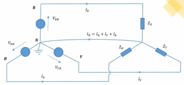
When the loads are balanced: ,
In this case, neutral wire is optional and can be eliminated. have to be
maintained so that the voltage is equal to ground voltage in neutral wire. This
makes sure there are no power losses in neutral wire.
Real-life Usage
Section titled “Real-life Usage”Most domestic loads are single-phase. In case of 3-phase domestic wiring, the single-phase loads are distributed among the 3 phases at the main distribution board.
Devices that have a 3-phase power input, doesn’t require a neutral line.
Per-phase Equivalent Circuit
Section titled “Per-phase Equivalent Circuit”Power, voltage, current, power factor are same for all phases.
When a 3-phase system is balanced, it is sufficient to consider only a single phase. The diagram showing the single-phase equivalent of the power system using standard symbols.
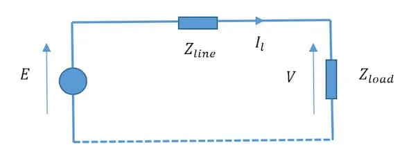
Here:
- - voltage across the source
- - voltage across the load
Here:
- - phase voltage
- - line voltage
- - line current
- - power factor
- The power can either be source power, load power, or transmission power losses.
Unbalanced 3-phase system
Section titled “Unbalanced 3-phase system”A 3-phase system becomes unbalanced, when load distribution is not equal among the phases. . Highly undesirable. Neutral wire is the return path for the line currents and is compulsory.
Large currents in the neutral wire could cause:
- If neutral wire have significant impedance, different points of the neutral wire will have different voltage
- Series voltage unbalances can happen if the neutral wire is broken
Each phase will be different. Complete system has to be considered when analyzing the circuit.